13 Results
View results:
Sort by:

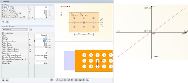
For a timber connection as shown in Figure 01, you can take into account the torsional spring rigidity (spring stiffness for rotation) of the connections. You can determine it by means of the slip modulus of the fastener and the polar moment of inertia of the connection.

In timber design, beams are often built from several timber elements. The individual elements can be connected with glue, nails, bolts, or dowels. A glued connection is to be assumed as rigid. In the case of dowel‑type fasteners, the joint is compliant (slip joint), and the cross‑section properties of the connected elements cannot be fully applied.

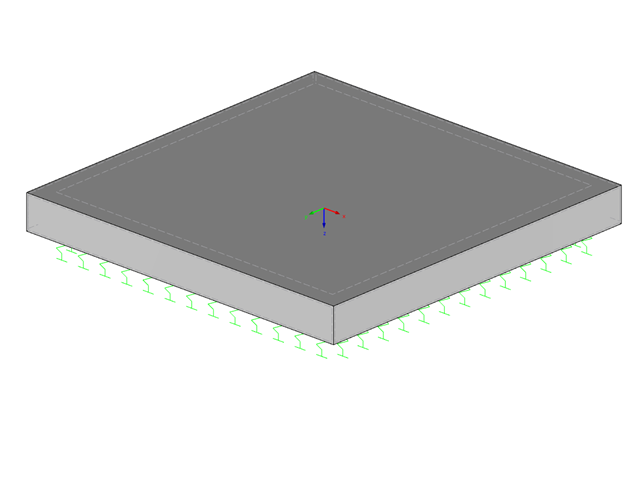
RFEM 5 allows you to use many different member nonlinearities for designing a model. In the following text, we look at an example of the use of the "slippage" member nonlinearity. The example is a simplified model of a concrete manhole with a square plan view.
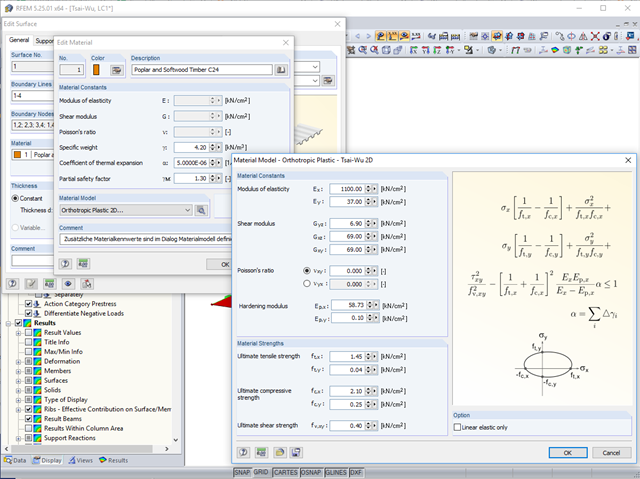
In RFEM, orthotropic plastic analyses using the Tsai‑Wu plasticity criterion have been possible for quite some time now. The hardening modulus Ep,x or Ep,y can be used to consider the hardening of the material during the iterative calculation.
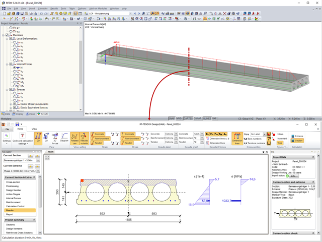
Prestressed concrete slabs consist of composite, uniaxially stressed hollow plates with a width of about 1.20 m. These elements are prestressed with pre-tension in a precast concrete plant. The precasting is usually done with slipformers. Due to the lesser self‑weight of the non‑solid slab and the existing prestress, these precast prestressed hollow core slabs show a lower deflection than loosely reinforced slabs made of solid concrete.

According to Clause 6.2.2 (6) of EN 1993‑1‑8:2010‑12, you can apply friction using the friction coefficient to design the shear capacity.

The calculation of timber panels is carried out on simplified member or surface structures. This article describes how to determine the required stiffness.
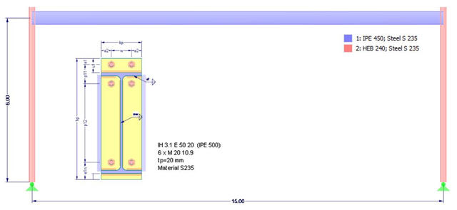
This article deals with the stiffness of standardized joints according to the DSTV (German Steel Construction Association)/DASt (German Committee for Structural Steelwork) standards, often used in steel construction, and its effects on structural analysis and design results according to DIN EN 1993-1-1.
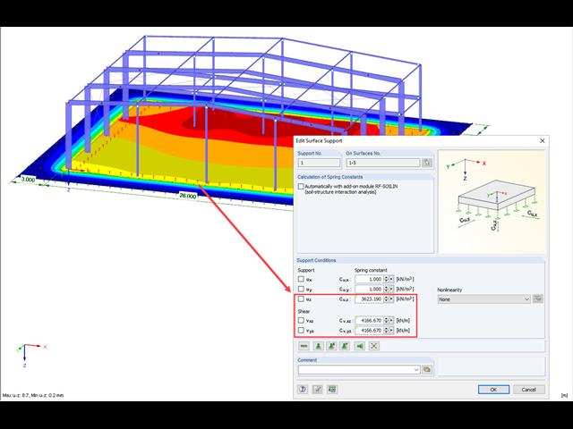
A previous article presented different variants of surface elastic foundations in addition to the traditional subgrade reaction modulus method. The following article describes another method for surface foundation. This method considers the adjacent ground areas by means of a foundation overlap. In this case, foundation parameters refer to the continuing works by Pasternak and Barwaschow.
A foundation is usually created in RFEM using the subgrade reaction modulus method. The reason for this is the relatively easy and straightforward manageability. Also, no iterative calculations are necessary and the computing time is relatively short. The subgrade reaction means that, for example, a foundation plate is loaded flat elastically.
In RF-JOINTS Timber – Steel to Timber, you can consider the possible minimum slippage of bolts in the case of guide pins. In RFEM, this slippage is taken into account using the flexibility in member end releases.
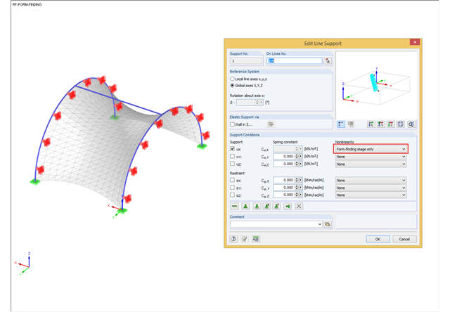
During the form-finding process, the slip modulus of a substructure is also taken into account when searching for the equilibrium state. You can also consider large deflections of supporting trusses or pure bending deformation of the edge beams when determining the membrane shape.
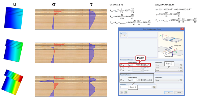
In order to represent the stiffness of the entire structure correctly, you can consider shear coupling between the ceiling and the downstand beam using the line release. This way, you can define a spring constant, thus avoiding the replacement system by using coupling members. The spring constant results from the shift modulus of the fastener, which can be determined according to EN 1995-1-1 or ANSI/AWC NDS, for example.